Pi GBC, Commande des moteurs Lego
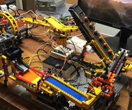
Nous avons vu comment démarrer nos moteurs Lego, comment détecter les billes. Il est temps de voir le mécanisme de communication entre l'Arduino et le Raspberry. Ce tutoriel va évoluer au fur et à mesure de mes tests avec différents matériels.
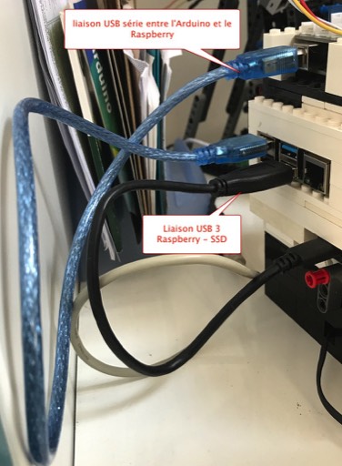
Dans le premier chapitre, je vous propose de découvrir la communication série entre l'Arduino et le Raspberry. Dans le second chapitre, nous allons utiliser une carte shield Ethernet avec une connexion UDP.
Dans le premier chapitre, je vous propose de découvrir la communication série entre l'Arduino et le Raspberry. Dans le second chapitre, nous allons utiliser une carte shield Ethernet avec une connexion UDP.
1 Communication série
1.1 Généralités
void setup()
{
    Serial.begin(9600); // set up Serial library at 9600 bps
}
Pour envoyer des données, nous utiliserons la fonction suivante.
void loop()
{
    Serial.println ("Detection,capteur7");
}
Côté Raspberry, nous utiliserons le langage Python. Pour utiliser la communication série, nous aurons besoin la librairie pySerial. Celle-ci est installée par défaut sur le Raspberry. Voici la fonction pour l'initialisation.
#!/usr/bin/python3

import serial

ser = serial.Serial()

def serialopen():
    ser.baudrate = 9600
    ser.port = '/dev/ttyACM0'
    ser.open()
    if ser.is_open:
        return True
Nous utiliserons une fonction pour ouvrir la communication série. Il faudra paramétrer la valeur du débit. On prendra le soin de mettre la même valeur que l'arduino. Il faut aussi sélectionner le port, normalement vous devriez avoir le même. Évitez l'exécution simultanée avec l'IDE Arduino sur le Raspberry car il y aura un conflit de port série.
La récupération des données se fera comme ci-dessous :
La récupération des données se fera comme ci-dessous :
if serialopen():
    while 1:
        result = ser.readline()
        print (chaine)
1.2 Un premier programme
Voici un exemple pratique, nous avons deux modules LEGO GBC piloté par le Raspberry. Ces deux modules ont un fonctionnement totalement différent. Le premier que l'on nommera Pinball utilise un convoyeur vertical et un mur blanc parsemé de picot. Avec ce module, une bille va parcourir ce module en 10 secondes environ et celui-ci pourra traiter 1 bille par seconde en mode continu. Le deuxième module est un convoyeur avec un fonctionnement original. Avec ce module, une bille va parcourir ce module en 50 secondes environ et celui-ci pourra traiter 4 billes par seconde en mode continu.
Il est bien évident, si on laisse les modules en fonctionnement continu, il y aura des temps de fonctionnement à vide pour le premier module. Avec les capteurs, vu précédemment, nous allons commander les moteurs en fonction d'un nombre de billes traité par chacun des modules.
Ce programme n'utilisera que deux capteurs optiques. Un bouton a été ajouté pour mettre à zéro les compteurs internes.
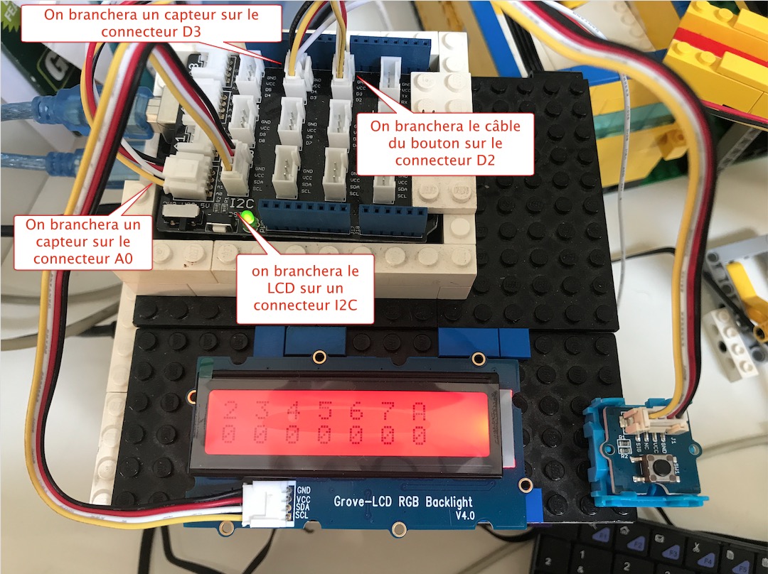
L'Arduino avec son shield Grove permettant un montage rapide des composants.
Voici le programme Arduino.
/*Interruption PCINT2 with I2C*/
#include <Wire.h>
#include "rgb_lcd.h"

rgb_lcd lcd;

const int colorR = 255;
const int colorG = 0;
const int colorB = 0;


volatile int opto2=0;
volatile int opto7=0;

const int buttonPin = 2;

// variables will change:
int buttonState = 0;

void pciSetup(byte pin)
{
    *digitalPinToPCMSK(pin) |= bit (digitalPinToPCMSKbit(pin));  // enable pin
    PCIFR  |= bit (digitalPinToPCICRbit(pin)); // clear any outstanding interrupt
    PCICR  |= bit (digitalPinToPCICRbit(pin)); // enable interrupt for the group
}

ISR(PCINT2_vect) // handle pin change interrupt for D2 to D7 here
{
  if (digitalRead(3) == LOW){
   opto2=opto2+1;
   Serial.println ("Detection,capteur2");
   }
}

ISR(PCINT1_vect) // handle pin change interrupt for A0 to A5 here
{
  if (digitalRead(A0) == LOW){
   opto7=opto7+1;
   Serial.println ("Detection,capteur7");
   }
}


void setup()
{

  lcd.begin(16, 2);
  lcd.setRGB(colorR, colorG, colorB);
  // initialize the pushbutton pin as an input:
  pinMode(buttonPin, INPUT);
  pciSetup(3);
  pciSetup(A0);
  lcd.print("2 3 4 5 6 7 A");
  Serial.begin(9600); // set up Serial library at 9600 bps
 }

void loop()
{
    // read the state of the pushbutton value:
    buttonState = digitalRead(buttonPin);

    // check if the pushbutton is pressed.
    // if it is, the buttonState is HIGH:
    if (buttonState == HIGH) {
       lcd.setCursor(0,1);
       String chaine = "                ";
       lcd.print(chaine);
        // RAZ:
        opto2=0;
        opto7=0;
    }
  lcd.setCursor(0,1);
  String chaine = String(opto1) + " " + String(opto2) + " " + String(opto3) + " " + String(opto4) + " " + String(opto5) + " " + String(opto6) + " " + String(opto7);
  lcd.print(chaine);
  delay(100);
}
Côté Raspberry, le programme Python servira à initialiser le démarrage du premier module GBC. Il comportera la logique de détection des billes et commandera les moteurs en fonction du nombre max de billes traités. Nous utiliserons le script Python précédent pour la commande des moteurs Lego.
#!/usr/bin/python3

import serial
import os

# initialisation des variables
ser = serial.Serial()
compteur2 = 0
compteur7 = 0

def serialopen():
    ser.baudrate = 9600
    ser.port = '/dev/ttyACM0'
    ser.open()
    if ser.is_open:
        return True

myCmd = '/home/pi/Documents/pi-gbc/python/commandmotor.py motor start 7'
os.system(myCmd)
if serialopen():
    while 1:
        result = ser.readline()
        chaine = result.decode("utf-8")
        titre,capteur = chaine.split(",")
        if capteur == "capteur2\r\n":
            print ("capteur2")
            compteur2 = compteur2 +1
            if compteur2 > 10:
                myCmd = '/home/pi/Documents/pi-gbc/python/commandmotor.py motor stop 6'
                os.system(myCmd)
                myCmd = '/home/pi/Documents/pi-gbc/python/commandmotor.py motor start 7'
                os.system(myCmd)
                compteur2 = 0
        if capteur == "capteur7\r\n":
            print ("capteur7")
            compteur7 = compteur7 +1
            if compteur7 > 10:
                myCmd = '/home/pi/Documents/pi-gbc/python/commandmotor.py motor stop 7'
                os.system(myCmd)
                myCmd = '/home/pi/Documents/pi-gbc/python/commandmotor.py motor start 6'
                os.system(myCmd)
                compteur7 = 0
Une vidéo pour voir le fonctionnement des modules.
00:00
/
00:00
2 Communication Ethernet
Dans ce chapitre, nous utiliserons un nouveau shield Ethernet pour Arduino. Il existe deux types de shield, un shield basé sur le composant Wiznet 5100 et le second basé sur le composant Microchip ENC28J60. Nous verrons la première carte, plus facile à programmer.
2.1 Le shield Ethernet
Première déconvenue avec l'utilisation conjointe du shield Grove, il faut obligatoirement positionner le shield Ethernet au dessus. Par conséquent, les connecteurs Grove ne sont plus accessibles. Il faudra enlever le shield Ethernet à chaque modification de câblage.
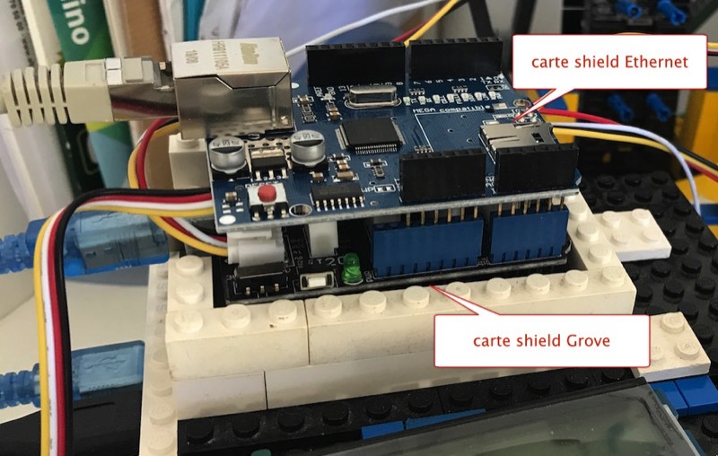
Les cartes shield en situation
2.2 Programmation avec l'Arduino
Il s'agit maintenant de communiquer avec le Raspberry pour envoyer les détections de billes. Nous utiliserons une connexion UDP sur la couche TCP/IP car plus facile à réaliser. Nous utiliserons une addresse IP fixe pour l'Arduino et nous devons connaître l'adresse IP du Raspberry recevant les trames. Deuxième déconvenue, nous ne pourrons plus utiliser les I/O suivants : le pin 4 utilisé par la carte SDRam, et les pins 10, 11, 12 et 13 utilisés pour la communication Ethernet.
La bibliothèque de cette carte est déjà intégrée dans l'IDE Arduino, il faudra la déclarer dans notre programme.
La bibliothèque de cette carte est déjà intégrée dans l'IDE Arduino, il faudra la déclarer dans notre programme.
/*bibliothèque pour la cate ethernet*/
#include <SPI.h>
#include <Ethernet.h>
#include <EthernetUdp.h>
Continuons par la déclaration des objets et variables. Le port de l'IP émetteur est 8888 et le port du récepteur est 20500.
//déclaration de l'objet Udp
EthernetUDP Udp;

/*tableau adresse mac*/
byte mac[] = {0x90, 0xA2, 0xDA, 0x0F, 0xDF, 0xAB};

/*tableau adresse IP*/
byte ip[] = {192, 168, 1, 123};

/*une autre solution pour déclarer une adresse IP*/
//affectation de l'adresse IP du Raspberry recevant les trames
IPAddress remoteIP(192,168,1,20);

//affectation des ports TCP
unsigned int localport = 8888;
unsigned int remotePort = 20500;
Initialisation de la carte Ethernet et de son protocole UDP.
void setup()
{
   …..
  // initialisation carte Ethernet
  Ethernet.begin (mac, ip);

  //on affiche l'adresse IP
  Serial.print("\nAdresse IP : ");
  Serial.println(Ethernet.localIP());

  //initialisation UDP
  Udp.begin(localport);
  ……
 }
Pour envoyer les messages via les interruptions, il suffira d'ajouter ces lignes.
if (digitalRead(A0) == LOW){
   ……..
   Udp.beginPacket(remoteIP, remotePort);
   Udp.println("Detection,capteur7");
   Udp.endPacket();
   ……..
   }
Voici le programme complet.
/*Interruption PCINT2 with I2C*/
#include <Wire.h>
#include "rgb_lcd.h"
/*bibliothèque pour la cate ethernet*/
#include <SPI.h>
#include <Ethernet.h>
#include <EthernetUdp.h>

//déclaration de l'objet Udp
EthernetUDP Udp;

/*tableau adresse mac*/
byte mac[] = {0x90, 0xA2, 0xDA, 0x0F, 0xDF, 0xAB};

/*tableau adresse IP*/
byte ip[] = {192, 168, 1, 123};

/*une autre solution pour déclarer une adresse IP*/
//affectation de l'adresse IP du Raspberry recevant les trames
IPAddress remoteIP(192,168,1,20);

//affectation des ports TCP
unsigned int localport = 8888;
unsigned int remotePort = 20500;

rgb_lcd lcd;

const int colorR = 255;
const int colorG = 0;
const int colorB = 0;


volatile int opto1=0;
volatile int opto2=0;
volatile int opto3=0;
volatile int opto4=0;
volatile int opto5=0;
volatile int opto6=0;
volatile int opto7=0;

const int buttonPin = 2;

// variables will change:
int buttonState = 0;

void pciSetup(byte pin)
{
    *digitalPinToPCMSK(pin) |= bit (digitalPinToPCMSKbit(pin));  // enable pin
    PCIFR  |= bit (digitalPinToPCICRbit(pin)); // clear any outstanding interrupt
    PCICR  |= bit (digitalPinToPCICRbit(pin)); // enable interrupt for the group
}

ISR(PCINT2_vect) // handle pin change interrupt for D2 to D7 here
{
  if (digitalRead(3) == LOW){
   opto2=opto2+1;
   Udp.beginPacket(remoteIP, remotePort);
   Udp.println("Detection,capteur2");
   Udp.endPacket();
   Serial.println ("Detection,capteur2");
   }

}

ISR(PCINT1_vect) // handle pin change interrupt for A0 to A5 here
{
  if (digitalRead(A0) == LOW){
   opto7=opto7+1;
   Udp.beginPacket(remoteIP, remotePort);
   Udp.println("Detection,capteur7");
   Udp.endPacket();
   Serial.println ("Detection,capteur7");
   }

}


void setup()
{
   Serial.begin(9600); // set up Serial library at 9600 bps
  // initialisation carte Ethernet
  Ethernet.begin (mac, ip);

  //on affiche l'adresse IP
  Serial.print("\nAdresse IP : ");
  Serial.println(Ethernet.localIP());

  //initialisation UDP
  Udp.begin(localport);
  lcd.begin(16, 2);
  lcd.setRGB(colorR, colorG, colorB);
  // initialize the pushbutton pin as an input:
  pinMode(buttonPin, INPUT);
  pciSetup(3);
  pciSetup(A0);
  lcd.print("2 3 4 5 6 7 A");
 }

void loop()
{
    // read the state of the pushbutton value:
    buttonState = digitalRead(buttonPin);

    // check if the pushbutton is pressed.
    // if it is, the buttonState is HIGH:
    if (buttonState == HIGH) {
       lcd.setCursor(0,1);
       String chaine = "                ";
       lcd.print(chaine);
        // RAZ:
        opto1=0;
        opto2=0;
        opto3=0;
        opto4=0;
        opto5=0;
        opto6=0;
        opto7=0;
    }
  lcd.setCursor(0,1);
  String chaine = String(opto1) + " " + String(opto2) + " " + String(opto3) + " " + String(opto4) + " " + String(opto5) + " " + String(opto6) + " " + String(opto7);
  lcd.print(chaine);
  delay(100);
}
Côté Raspberry, Il faudra modifier le programme pour recevoir les trames UDP.
#!/usr/bin/python3

import socket
import os

# initialisation des variables
buf=1024
adresse=('',20500)

compteur2 = 0
compteur7 = 0


myCmd = '/home/pi/Documents/pi-gbc/python/commandmotor.py motor start 7'
os.system(myCmd)
socketserveur=socket.socket(socket.AF_INET, socket.SOCK_DGRAM)
socketserveur.bind(adresse)
print ("serveur actif")

while True:
    # attente d'une nouvelle connexion
    # et enregistrement de la requete et de l'adresse du demandeur
    requete, adresseclient = socketserveur.recvfrom(buf)
    if not requete:
        break
    result = requete.strip()
    print ("received data:", result)
    chaine = result.decode("utf-8")
    titre,capteur = chaine.split(",")
    if capteur == "capteur2":
        print ("capteur2")
        compteur2 = compteur2 +1
        if compteur2 > 10:
            myCmd = '/home/pi/Documents/pi-gbc/python/commandmotor.py motor stop 6'
            os.system(myCmd)
            myCmd = '/home/pi/Documents/pi-gbc/python/commandmotor.py motor start 7'
            os.system(myCmd)
            compteur2 = 0
    if capteur == "capteur7":
        print ("capteur7")
        compteur7 = compteur7 +1
        if compteur7 > 10:
            myCmd = '/home/pi/Documents/pi-gbc/python/commandmotor.py motor stop 7'
            os.system(myCmd)
            myCmd = '/home/pi/Documents/pi-gbc/python/commandmotor.py motor start 6'
            os.system(myCmd)
            compteur7 = 0
Nous pouvons ajouter une fonctionnalité supplémentaire comme un serveur Web. Il nous permettra de visualiser l'état des capteurs avec un navigateur. On en profite pour transformer les variables en tableau de capteur. Voici le programme complet.
/*Interruption PCINT2 with I2C*/
#include <Wire.h>
#include "rgb_lcd.h"
/*bibliothèque pour la cate ethernet*/
#include <SPI.h>
#include <Ethernet.h>
#include <EthernetUdp.h>

//déclaration de l'objet Udp
EthernetUDP Udp;

/*tableau adresse mac*/
byte mac[] = {0x90, 0xA2, 0xDA, 0x0F, 0xDF, 0xAB};

/*tableau adresse IP*/
byte ip[] = {192, 168, 1, 123};

/*une autre solution pour déclarer une adresse IP*/
//affectation de l'adresse IP du Raspberry recevant les trames
IPAddress remoteIP(192,168,1,20);

//affectation des ports TCP
unsigned int localport = 8888;
unsigned int remotePort = 20500;

//affectation port 80
EthernetServer serveur(80);

rgb_lcd lcd;

const int colorR = 255;
const int colorG = 0;
const int colorB = 0;


volatile int opto[] = {0, 0, 0, 0, 0, 0, 0};

const int buttonPin = 2;

// variables will change:
int buttonState = 0;

void pciSetup(byte pin)
{
    *digitalPinToPCMSK(pin) |= bit (digitalPinToPCMSKbit(pin));  // enable pin
    PCIFR  |= bit (digitalPinToPCICRbit(pin)); // clear any outstanding interrupt
    PCICR  |= bit (digitalPinToPCICRbit(pin)); // enable interrupt for the group
}

ISR(PCINT2_vect) // handle pin change interrupt for D2 to D7 here
{
  /*if (digitalRead(2) == LOW){
   opto1=opto1+1;
  }*/
  if (digitalRead(3) == LOW){
   opto[2]=opto[2]+1;
   Udp.beginPacket(remoteIP, remotePort);
   Udp.println("Detection,capteur2");
   Udp.endPacket();
   Serial.println ("Detection,capteur2");
   }
  /*if (digitalRead(4) == LOW){
   opto3=opto3+1;
  }
  if (digitalRead(5) == LOW){
   opto4=opto4+1;
  }
  if (digitalRead(6) == LOW){
   opto6=opto5+1;
  }
  if (digitalRead(7) == LOW){
   opto6=opto6+1;
  }*/

}

ISR(PCINT1_vect) // handle pin change interrupt for A0 to A5 here
{
  if (digitalRead(A0) == LOW){
   opto[6]=opto[6]+1;
   Udp.beginPacket(remoteIP, remotePort);
   Udp.println("Detection,capteur7");
   Udp.endPacket();
   Serial.println ("Detection,capteur7");
   }

}


void setup()
{
   Serial.begin(9600); // set up Serial library at 9600 bps
  // initialisation carte Ethernet
  Ethernet.begin (mac, ip);

  //on affiche l'adresse IP
  Serial.print("\nAdresse IP : ");
  Serial.println(Ethernet.localIP());

  //initialisation UDP
  Udp.begin(localport);
  //on initialise le serveur HTTP
  serveur.begin();

  lcd.begin(16, 2);
  lcd.setRGB(colorR, colorG, colorB);
  // initialize the pushbutton pin as an input:
  pinMode(buttonPin, INPUT);
  pciSetup(3);
  pciSetup(A0);
  lcd.print("2 3 4 5 6 7 A");
 }

void loop()
{
    // read the state of the pushbutton value:
    buttonState = digitalRead(buttonPin);

    // check if the pushbutton is pressed.
    // if it is, the buttonState is HIGH:
    if (buttonState == HIGH) {
       lcd.setCursor(0,1);
       String chaine = "                ";
       lcd.print(chaine);
        // RAZ:
        for (int p=0;p<7;p++){
          opto[p] = 0;
        }
    }
  lcd.setCursor(0,1);
  String chaine = String(opto[0]) + " " + String(opto[1]) + " " + String(opto[2]) + " " + String(opto[3]) + " " + String(opto[4]) + " " + String(opto[5]) + " " + String(opto[6]);
  lcd.print(chaine);
  EthernetClient client = serveur.available();
  if (client) {
    Serial.println("Client en ligne\n");
    if (client.connected()) {
      while (client.available()) {
        char c=client.read();
        Serial.write(c);
        delay(1);
      }
      //réponse au client
      client.println("HTTP/1.1 200 OK");
      client.println("Content-Type: text/html; charset=ascii ");
      client.println("Connection: close");
      client.println("Refresh: 5");
      client.println();
      client.println("<!DOCTYPE HTML>");
      client.println("<html>");
      client.println("<head>");
      client.println("<title>Pi-GBC Demo</title>");
      client.println("</head>");
      client.println("<body>");
      client.println("<!DOCTYPE HTML>");
            client.println("<h1>Etat des capteurs</h1>");
      client.println("<hr>");
      for (int p=0;p<7;p++){
        client.print("Capteur");
        client.print(p+1);
        client.print(" : ");
        client.print(opto[p]);
        client.print("<br>");
      }
      client.println("<hr>");
      client.println("</body>");
      client.println("</html>");
      client.stop();
      Serial.println("Fin de communication avec le client");
    }

  }

  delay(100);
}
Ci-dessous l'affichage du serveur web Arduino.
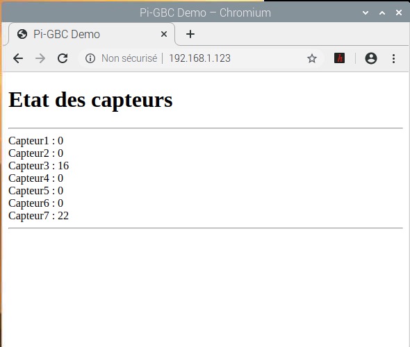
Visualisation du serveur HTTP de l'Arduino, la page est rafraîchie toutes les cinq secondes.
Et pour finir une petite vidéo.
00:00
/
00:00
Dernière modification: 30/07/2023